
 简体中文
简体中文 English
 Русский
You have the new valve in hand, the cable is pulled, and the drawing on the replacement body shows two squares, two flow arrows, and a small coil symbol. The only thing missing is a clear answer to a simple question: which wire goes where? A solenoid valve wiring schematic settles that question before you energize the circuit. Read correctly, it tells you the supply voltage, the valve position logic, the connector pin functions, and the grounding requirements. Skip it, and you risk a burned coil, a chattering valve, or a machine that refuses to start.
This guide explains how to read solenoid valve diagrams, how to wire the most common DIN 43650 connectors, how to choose a valve body material that matches your environment, and how to avoid the faults that come from a wiring plan that did not match the schematic.
Content
- 1 Why a Wiring Schematic Matters Before You Touch the Valve
- 2 Reading the Schematic: Squares, Arrows, and Symbols
- 3 Wiring Step by Step: DIN 43650A and Direct Connections
- 4 Response Time and Duty Cycle: What the Diagram Does Not Show
- 5 Material Selection: The Wiring Is Only Half of the Reliability Story
- 6 Common Wiring Faults and How to Diagnose Them
- 7 Frequently Asked Questions on Solenoid Valve Wiring and Schematics
Why a Wiring Schematic Matters Before You Touch the Valve
Read the diagram before you wire, not after. In industrial practice, most solenoid coil failures trace back to a simple mismatch between the coil rating and the supply, a reversed polarity connection on a DC valve, or a missing protective earth connection. The schematic is the fastest tool to prevent all three.
Keep these three rules in mind whenever you look at a solenoid valve wiring drawing:
- Verify the coil voltage exactly as printed on the nameplate (for example, DC24V, AC110V, AC220V), not on the color of the coil housing.
- Confirm whether the circuit is DC or AC. DC coils are polarity-sensitive at the semiconductor level, so the positive and negative leads must not be swapped when a relay or PLC output is used.
- Check the connector standard. Most industrial pneumatic valves use a DIN 43650 socket with two or three pins; the pinout on the schematic tells you which pin is live, which is neutral, and which is ground.
If the circuit includes an inductive load such as a relay or a solenoid, plan a flyback diode for DC and a varistor or RC snubber for AC. Without it, the switching-off voltage spike can damage the PLC output.
Reading the Schematic: Squares, Arrows, and Symbols
The symbol on a valve body is a functional drawing, not a physical one. Each square represents one position of the valve. A 2/2-way valve has two squares and two ports; a 5/2-way valve has two squares and five ports. The arrows inside the squares show which ports are connected when the valve is in that position, and a T-shaped line marks a blocked port.
- Positions: the number of squares tells you how many states the valve can switch between.
- Flow paths: arrows connect ports in each position; if you see P to A, the supply is directed to the working port.
- Actuators: the solenoid is drawn as a rectangle with a diagonal line; a spring is a zigzag symbol on the opposite side for spring-return valves.
- Port labels: common markings are P (supply), A and B (working), and R/S or T (exhaust). ISO 5599 numbers, 1, 2, 4, 3, 5, follow the same logic.
A normally closed (NC) valve shows the spring returning the box so that P is blocked; a normally open (NO) valve shows P connected to the working port in the rest position. The wiring diagram printed on the coil or the nameplate confirms which condition your process needs.
Wiring Step by Step: DIN 43650A and Direct Connections
Most pneumatic solenoid valves in industrial automation use a DIN 43650A connector, also called a Form A plug. It is a rectangular black plug with a single screw in the center and either two or three pins. For a DC coil, the pinout is almost always the same:
| Pin | Function | Wire color | Connection note |
|---|---|---|---|
| 1 | Coil positive / live | Brown | Connect to +24 VDC or phase of AC supply |
| 2 | Coil negative / neutral | Blue | Connect to 0 VDC or neutral of AC supply |
| Ground | Protective earth | Green/yellow | Required for metal-bodied valves |
Wire in this order:
- Switch off the supply and lock out the circuit.
- Check the coil rating on the nameplate and measure the supply voltage with a multimeter.
- Open the DIN plug and identify pins 1, 2, and the ground clamp.
- Connect pin 1 to the positive or phase conductor, pin 2 to the negative or neutral, and the ground clamp to the protective earth.
- Use a cable gland with the correct IP rating, and tighten the center screw so it presses the plug onto the coil pins.
- Energize the circuit and test the valve while watching for clicking, buzzing, or heating.
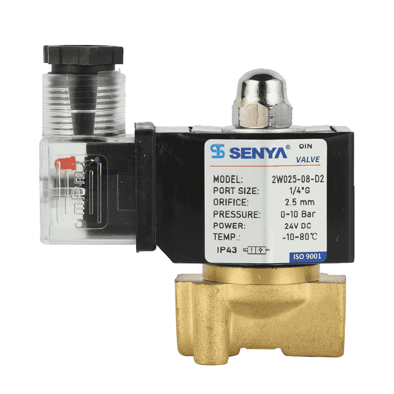
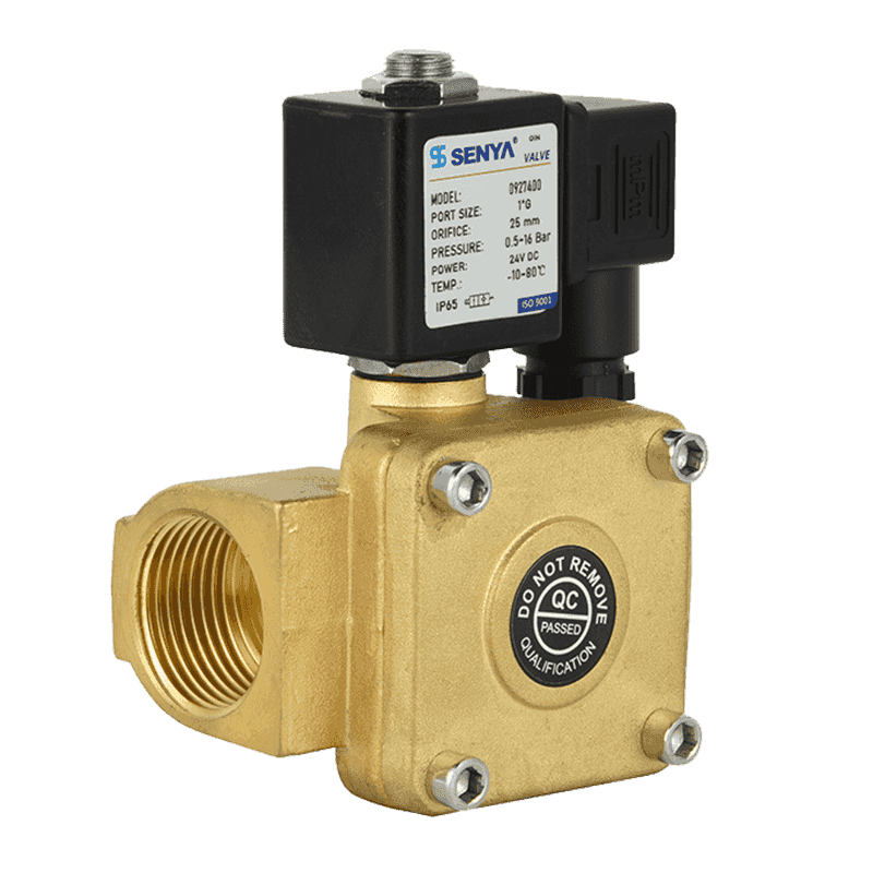
For simple media such as air, water, and light oil, a general-purpose 2W series brass solenoid valve with a standard DIN coil is a practical choice. If this is your first installation, our installation and debugging guide covers the full sequence from mounting to first power-up.
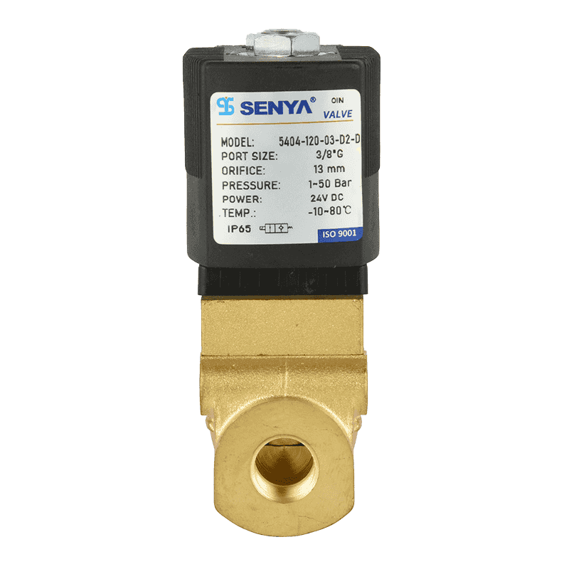
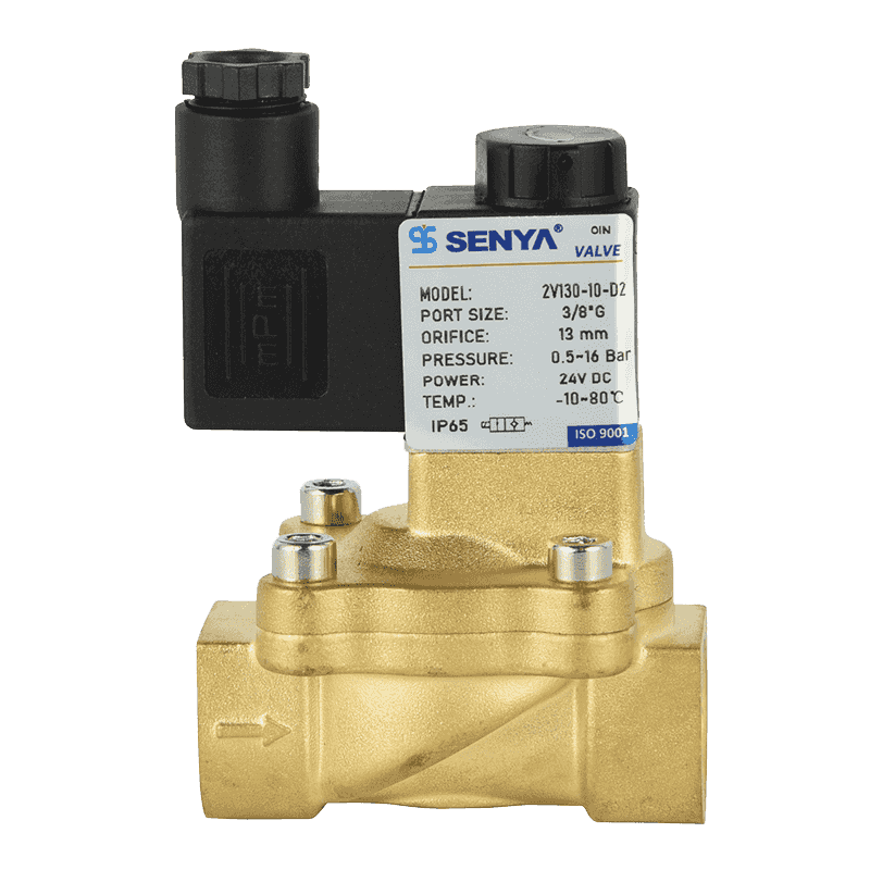
 A large water control 2/2 ways brass solenoid valve with high Impurity toleranceNingbo SENYA Pneumatic Technology Co., Ltd. is China A large water control 2/2 ways brass solenoid valve with high Impurity tolerance cap...View Product →
Control Options: Switch, Relay, Timer, or PLC
A manual switch is the most direct control, but automation normally uses a relay or a PLC output. When you control a DC solenoid with a PLC, install a flyback diode across the coil terminals to protect the output transistor. When you use AC, add a varistor across the contactor or relay contacts. Timer-based cycling is allowed only within the duty cycle of the coil.
Response Time and Duty Cycle: What the Diagram Does Not Show
A wiring schematic tells you how to connect the coil, but it does not tell you how fast the valve responds or how long it can stay energized. Those numbers live on the datasheet. Response time is the interval between the electrical command and the completion of the movement; duty cycle is the percentage of time the coil is energized in one cycle.
Two practical consequences follow. First, if your application cycles faster than the response time of the valve, the flow will never fully open. Second, if the coil is energized longer than its duty cycle, the temperature rises quickly and the insulation degrades. For continuous running, choose a 100% ED coil; many pulse valves and intermittent applications can use lower ratings.
Material Selection: The Wiring Is Only Half of the Reliability Story
The same electrical connection can last for years or fail within weeks, and the difference is often the valve body material. The coil and connector must suit the electrical environment, but the body must suit the media and the surrounding conditions. A valve that handles demineralized water, saline washdown, outdoor moisture, or aggressive chemicals needs a different construction than one that simply switches dry air.
Brass remains the workhorse for neutral air, water, and light oil. When the environment is wet or wash-down is frequent, a SUS304 stainless steel solenoid valve offers higher corrosion resistance and keeps the electrical enclosure cleaner. For outdoor panels, irrigation, or spray applications where rain and humidity are expected, a waterproof 2WW series solenoid valve protects the coil and the connection point. If your wiring plan has special voltage requirements or mixed media, contact our engineering team before you buy.
 Music fountain submerged water column control valve2/2 ways solenoid valve BrassNingbo SENYA Pneumatic Technology Co., Ltd. is China Music fountain submerged water column control valve2/2 ways solenoid valve Brass sol...View Product →
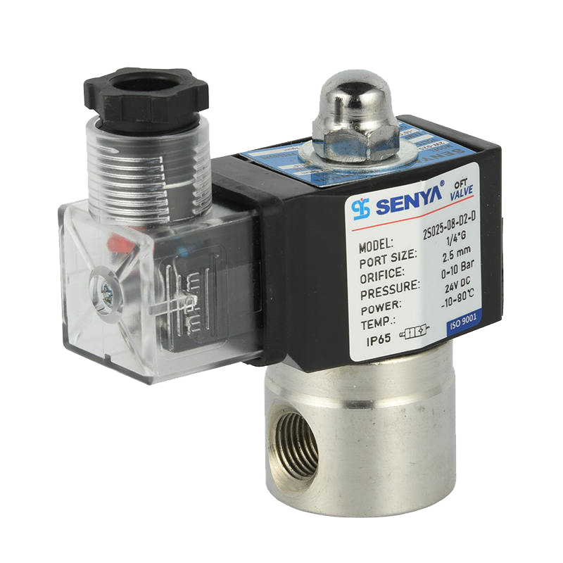
 Direct acting 2/2 ways stainless steel acid and alkali resistance normally closeNingbo SENYA Pneumatic Technology Co., Ltd. is China Direct acting 2/2 ways stainless steel acid and alkali resistance normally closed so...View Product →
Common Wiring Faults and How to Diagnose Them
When a valve is correctly specified but misbehaves after installation, the wiring is the first place to look. The table below orders the usual suspects from the most common to the most overlooked.
| Symptom | Likely cause | Check |
|---|---|---|
| Valve does not energize | No supply voltage, blown fuse, or open coil | Measure voltage at pins 1 and 2; measure coil resistance |
| Coil gets hot | Wrong voltage or duty cycle exceeded | Match coil rating to supply; shorten on-time |
| Intermittent operation | Loose DIN connector or oxidized pin | Clean pins and retighten center screw |
| Humming or buzzing | Low voltage on AC coil or binding plunger | Check supply stability; remove debris |
| Repeated coil burnouts | Missing flyback suppression or power surge | Add suppression diode or varistor |
| Valve opens slowly | Undersized cable or low pressure | Increase conductor size; check supply pressure |
Always start diagnosis with the multimeter at the connector, not at the valve. If the voltage is correct at the plug but the coil is still dead, the fault is inside the coil or in the wiring between the plug and the coil. No schematic can replace a good measurement.
Frequently Asked Questions on Solenoid Valve Wiring and Schematics
Solenoid valves are usually rated for AC 110V, AC 220V, DC 12V, or DC 24V. The exact rating is printed on the coil; always confirm it before connecting a power supply.
Yes, if the PLC output supplies the same voltage and enough current. Otherwise, use a relay. For DC coils, add a flyback diode to protect the output transistor.
A 2/2 valve has two ports and two positions for simple open/close duty. A 5/2 valve has five ports and two positions, used to switch the direction of a pneumatic cylinder. The schematic shows the difference in the number of boxes and ports.
Each square is one valve position; arrows inside show the flow paths; the solenoid symbol on the side indicates how the valve is actuated. Port labels such as P, A, B, and exhaust identify each connection.
Match the DIN 43650 form (A, B, or C) to the coil socket, select the correct pin count, and choose a cable with an IP rating suitable for the environment. For outdoor or wash-down areas, use a waterproof connector.
Lifespan depends on duty cycle, lubrication, media cleanliness, and voltage stability. With filtered air and stable power, millions of cycles are normal; keep the air dry and check the coil temperature periodically.
.png?imageView2/2/w/326/h/326/format/jpg/q/75)
.png?imageView2/2/w/326/h/326/format/jpg/q/75)
.png?imageView2/2/w/326/h/326/format/jpg/q/75)
.png?imageView2/2/w/326/h/326/format/jpg/q/75)
.png?imageView2/2/w/326/h/326/format/jpg/q/75)