
 简体中文
简体中文 English
 Русский
A cell stops, the PLC waits, and every downstream station slows to the speed of one worn cylinder. That scenario repeats daily on packaging lines and assembly cells when an actuator was sized for nominal force but not for real friction, side loads, or a degraded seal. In automation systems, the cylinder is no longer a commodity part; it directly sets throughput, repeatability, and machine uptime.
Specialized industrial cylinders — actuators selected and specified for a defined force, stroke, speed, duty cycle, and operating environment — are the most effective lever a machine builder has for reliability. This guide explains how to choose, apply, and maintain them, with a practical focus on the pneumatic cylinders that dominate industrial automation.
Content
- 1 Pneumatic, Hydraulic, or Electric: The Real Trade-offs
- 2 Sizing a Cylinder: Force First, Then Stroke and Cushioning
- 3 Standard Cylinder Ranges: Which One Fits the Application
- 4 Anatomy of a Double-Acting Cylinder: What Each Part Does
- 5 Adapting Cylinders to Harsh Automation Environments
- 6 Integration: Sensors, Valves, and Manifolds
- 7 Maintenance That Protects Cylinder Life
- 8 Frequently Asked Questions
Pneumatic, Hydraulic, or Electric: The Real Trade-offs
Before selecting a specialized cylinder, decide the actuator technology. Each family has a clear performance envelope, and "specialized" in practice means matching the technology to the motion profile.
| Criterion | Pneumatic | Hydraulic | Electric |
|---|---|---|---|
| Force density | Moderate; standard cylinders deliver from a few hundred newtons up to around 10 kN at 6-8 bar | Very high; 100 kN and above is routine | High; ball-screw actuators commonly reach 10-50 kN |
| Speed | Fast; 0.1-1.5 m/s is typical | Moderate; usually 0.1-0.5 m/s | Fast and programmable, but system-dependent |
| Positioning precision | Repeatable with stops or sensors, typically 0.1-1 mm | Precise with servo valves, typically 0.01-0.1 mm | Very precise with encoders, typically 0.01-0.05 mm |
| Environment sensitivity | Needs filtered, dry air; temperature limited by seals | Susceptible to leaks and oil contamination | Clean, but sensitive to heat, moisture, and shock |
| Cost and maintenance | Low initial cost; simple, fast maintenance | Higher cost; pump and filtration upkeep | Higher initial cost; low running cost, more complex controls |
Conclusion: for fast, repetitive, cost-sensitive motion, pneumatic cylinders remain the default choice. Hydraulics earn their place where force dominates; electric actuators where precision dominates. That is why most specialized industrial cylinders in automation systems are pneumatic — and why the rest of this guide concentrates on them.
Sizing a Cylinder: Force First, Then Stroke and Cushioning
Start with the force equation that every automation engineer uses: F = P x A, where P is the supply pressure and A is the effective piston area. For a circular bore, A = pi/4 x D², with D the bore diameter. At a 6 bar supply (0.6 MPa), the theoretical push force climbs steeply as the bore grows:
In practice, multiply the required force by a safety factor of 1.25 to 1.3 to cover seal friction, side loads, pressure drops in long lines, and wear. Then select the next standard bore size. On the pulling stroke, remember that the rod reduces the effective piston area, so pull force is several percent lower than push force for the same bore.
Long strokes bring a second check: an unsupported rod can buckle. If the stroke exceeds roughly ten times the rod diameter, verify the rod's column strength or add a guide. High-speed strokes above about 0.5 m/s also need adjustable cushioning at both ends; without it, the piston slams into the end cap and shortens seal and bearing life.
A full worked procedure, including stroke and cushioning checks, is available in our step-by-step guide to choosing pneumatic cylinder size and specifications. When the calculation points to a standard actuator, ISO 15552 pneumatic cylinders offer the widest selection of interchangeable mounts, strokes, and options.
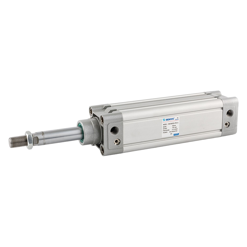 Custom ISO15552 pneumatic cylinder Suppliers, CompanyAs a China ISO15552 pneumatic cylinder suppliers and ISO15552 pneumatic cylinder Company, Ningbo SENYA Pneumatic Technology Co., Ltd. off...View Product →
Standard Cylinder Ranges: Which One Fits the Application
Specialized does not always mean custom. Most automation tasks are covered by standardized pneumatic cylinder series with known dimensions, mounting styles, and performance data. Choosing a standard range shortens delivery time, simplifies spare parts management, and gives the control engineer documented performance values to design against.
| Standard | Bore range | Typical use |
|---|---|---|
| ISO 15552 | 32-320 mm | General automation, machine tools, heavy transfer and clamping applications |
| ISO 21287 | 20-125 mm | Compact installations, short strokes, high-frequency cycling |
| ISO 6432 | 8-25 mm | Miniature applications: small parts handling, fixture clamping, medical devices |
Beyond these standards, application-specific series fill the gaps. For medium-duty automation, SC series rod pneumatic cylinders combine a rugged round body with simple mounting and economical pricing. Where space is tight and strokes are short, MAL series mini cylinders supply the compact force that precision assembly stations require.
 An automated cylinder that replaces manual simulation of mechanical output ManufNingbo SENYA Pneumatic Technology Co., Ltd. is China An automated cylinder that replaces manual simulation of mechanical output manufactu...View Product →
 Tie rod type air cylinder Pneumatic actuator for fast and flexible lubrication Ningbo SENYA Pneumatic Technology Co., Ltd. is China Tie rod type air cylinder Pneumatic actuator for fast and flexible lubrication manu...View Product →
Reading the Force Curves
The same cylinder family behaves differently as line pressure changes. The chart below shows theoretical push force for three common bores between 4 and 8 bar — the range where most automation systems operate.
Anatomy of a Double-Acting Cylinder: What Each Part Does
A specialized cylinder earns its name in the details of sealing, guiding, and sensing. The diagram below shows the load-bearing structure of a typical double-acting pneumatic cylinder.
Two details matter most for automation. First, the magnetic piston band enables non-contact position sensing: a magnetic switch mounted on the barrel detects the piston without mechanical contact, eliminating drift and wear. Second, the rod seal and wiper pair protects the cylinder from outside contamination while holding internal pressure at rated levels; their quality determines how many millions of cycles the cylinder can complete.
Adapting Cylinders to Harsh Automation Environments
Washdown zones, welding cells, food lines, and dusty transfer systems punish ordinary cylinders. The first question is not which bore to choose but which materials and seals will survive the environment.
- Corrosive or washdown areas: choose stainless steel barrels and rods (304/316 grade) with IP65 or higher protection and food-grade lubricants.
- High-temperature zones: standard nitrile seals suit around 0-70°C; PTFE or FKM seals extend the range well above 150°C for oven and welding applications.
- Dusty or abrasive atmospheres: metal scrapers, bellows, or purge-air fittings keep particles away from the rod seal.
- High humidity or chemicals: hard-anodized or ceramic-coated rods resist surface corrosion that would otherwise destroy the seal.
These adaptations raise cost, so specify them only where the process demands. A useful starting point is to understand the main causes of pneumatic cylinder wear; most early failures trace back to contamination, poor air quality, or misalignment rather than to the cylinder itself. Manufacturers that combine precision machining with automated digital test platforms — as SENYA describes its production lines — apply the same material and quality logic to cylinders built for demanding duty.
Integration: Sensors, Valves, and Manifolds
A cylinder becomes specialized when the control chain around it matches its speed and precision. Three decisions matter:
- Position feedback: magnetic switch sensors on the barrel change state when the piston band passes; this gives the PLC reliable end-of-stroke signals in milliseconds.
- Valve selection: the directional control valve determines response time. Larger flow capacity and shorter response times shorten cycle time; oversized valves, however, waste air and can hammer the cushioning.
- Manifold mounting: grouping valves on a manifold cuts wiring, tubing, and leak points while shrinking the footprint of the control cabinet.
For synchronized motion, feed the same supply pressure to both sides of the cylinder and let a 5/2-way valve switch the exhaust — a simple, reliable scheme used across packaging, material handling, and machine tool automation.
Maintenance That Protects Cylinder Life
The single biggest factor in cylinder longevity is the quality of the compressed air. Filtered, regulated, and lubricated air prevents most premature seal wear.
- Condition the air with an FRL unit set to the pressure used in the force calculation, typically 5-8 bar.
- Inspect the rod surface and seals during scheduled stops; scratches or embedded dirt are early warning signs.
- Check and adjust cushioning screws so the piston slows before contacting the end cap.
- Listen for creeping movement, noise, or long response delays — these indicate internal leakage or worn seals.
- Replace seal kits with original parts and apply the manufacturer's recommended lubricant.
A disciplined routine is easier than it sounds. Our five-step cylinder maintenance manual details what to inspect and how often, so uptime stays predictable even on continuous three-shift lines.
Frequently Asked Questions
Q1: How do I choose the right bore size for my cylinder?
Calculate the required thrust with F = P x A, add a 25-30% safety margin for friction and side loads, then choose the next standard bore size. Never forget the pull stroke, where the rod reduces the effective area.
Q2: What is the difference between ISO 15552 and ISO 21287 cylinders?
ISO 15552 covers full-profile tie-rod cylinders from 32 to 320 mm bore with worldwide interchangeable dimensions. ISO 21287 defines compact cylinders with much shorter overall length for the same bore, ideal for limited spaces.
Q3: How many cycles can a pneumatic cylinder complete?
With clean, lubricated air, correct sizing, and working cushioning, standard industrial cylinders routinely reach several million cycles. Contamination and impact loading are the two fastest ways to shorten that life.
Q4: Can cylinders be customized with special strokes, seals, or materials?
Yes. Custom strokes, PTFE or FKM seals for high temperature, stainless steel bodies and rods for washdown, and special rod ends are common options. Share your operating pressure, temperature, stroke, and environment with the manufacturer to get a matched solution.
.png?imageView2/2/w/326/h/326/format/jpg/q/75)
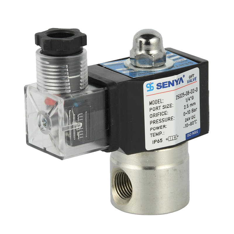
.png?imageView2/2/w/326/h/326/format/jpg/q/75)
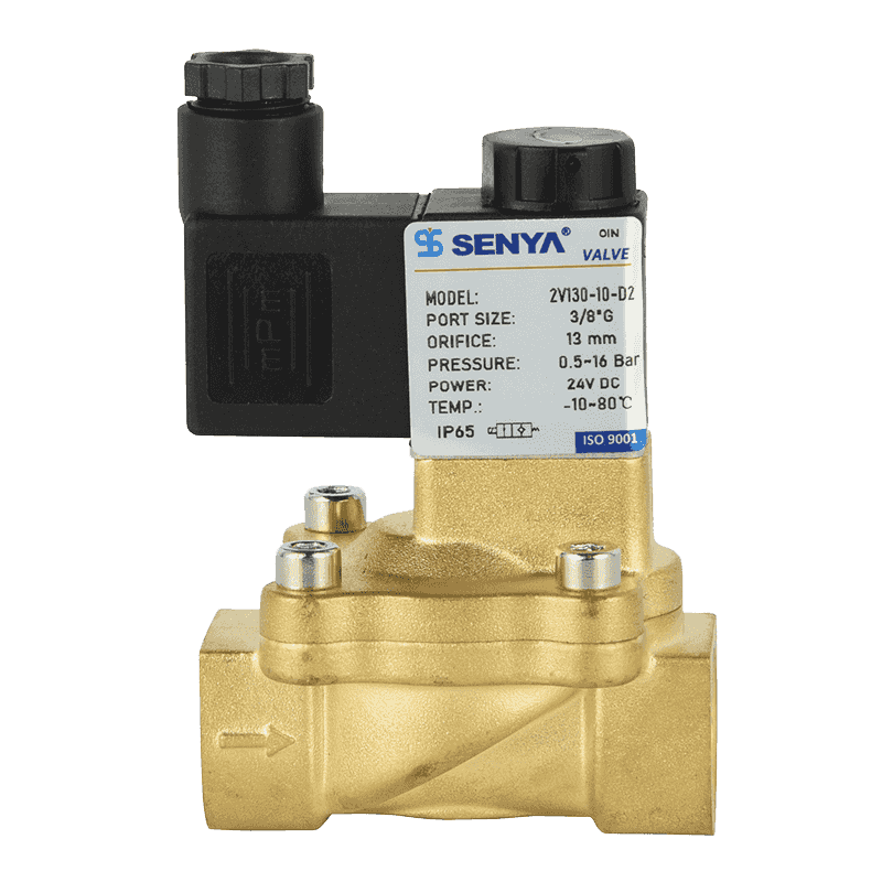
.png?imageView2/2/w/326/h/326/format/jpg/q/75)
.png?imageView2/2/w/326/h/326/format/jpg/q/75)
.png?imageView2/2/w/326/h/326/format/jpg/q/75)