
 简体中文
简体中文 English
 Русский
A production line stops mid-cycle. The technician finds the solenoid valve, sees the indicator LED glowing, and assumes the coil is energised. It is not. On many valve connectors the lamp is bridged across the supply terminals rather than across the coil, so a plug fitted 180 degrees out can light the indicator while the coil itself sits on an open circuit.
That is why a solenoid valve wiring diagram deserves to be drawn properly. It is not only a picture of which wire goes where. It separates three circuits that are routinely confused with one another:
- the coil circuit inside the valve connector, which carries the switching current;
- the control circuit in the panel, which decides when that current flows;
- the protective earth, which is a safety circuit and belongs to neither of the other two.
Get the first two right and the valve works. Get the third wrong and it may still work, right up to the day it does not.
Content
- 1 Read the Coil Nameplate Before You Draw Anything
- 2 Inside the Valve Connector: Wiring the Coil Circuit
- 3 AC and DC Coils Behave Differently on the Same Diagram
- 4 The Control Side: PLC Outputs, Relays and Suppression
- 5 Wet, Outdoor and Washdown Installations
- 6 Commissioning Checks and the Faults That Follow Bad Wiring
- 7 Frequently Asked Questions
- 7.1 Q1. What are the wire colours on a solenoid valve?
- 7.2 Q2. Does a solenoid valve have polarity?
- 7.3 Q3. Why does a solenoid valve coil burn out?
- 7.4 Q4. Do I need a flyback diode on a DC solenoid valve?
- 7.5 Q5. What is the pinout of a DIN 43650 Form A plug?
- 7.6 Q6. How many amps does a 24 V solenoid valve draw?
Read the Coil Nameplate Before You Draw Anything
Every wiring decision starts at the coil nameplate. A typical industrial coil carries six or seven fields, and each one changes either what you draw or what you order.
| Nameplate field | What it tells you | What it changes in the wiring |
|---|---|---|
| Rated voltage and supply type | For example 24 VDC, 110 VAC 50/60 Hz, 230 VAC 50/60 Hz | A coil is built for one supply family. A 230 VAC coil fed 24 VDC will not pull in; a 24 VDC coil fed 230 VAC usually fails at once. |
| Inrush and holding VA (AC) or power in W (DC) | Peak current at switch-on, steady current afterwards | Fuse rating, relay contact rating, cable cross-section and PLC output type |
| Duty cycle (ED) | Continuous, usually marked 100% ED, or intermittent | Whether the coil may be held energised or needs an interlock or timer |
| Protection class (IEC 60529) | IP65 for a gasketed plug, IP67 for a moulded cable | Gland, gasket and cable selection |
| Connector standard and terminal marking | DIN 43650 Form A (18 mm), Form B (10 mm), Form C (8 mm) or 6.3 mm spade terminals, plus the numbers moulded in the plug | The plug, gasket and spare coil you order, and the pinout you draw |
Inside the Valve Connector: Wiring the Coil Circuit
The Form A plug is the most common interface on industrial solenoid valves, and it is also where most wiring mistakes happen. The sequence below applies to any gasketed plug.
- Isolate the circuit and lock it off, then prove dead with a meter at the coil terminals rather than at the panel.
- Confirm the connector standard and the supply: line and neutral, or positive and negative.
- Prepare the cable so the earth conductor is slightly longer than the live cores, so it takes the strain last if the cable is pulled.
- Terminate the coil supply on the two coil contacts and the cable earth on the earth contact.
- Seat the flat gasket squarely on the coil terminal block before fitting the plug. A gasket that is missing, twisted or compressed is the usual reason water ends up inside a plug.
- Tighten the centre screw to the torque moulded on the housing. Over-tightening cracks the housing; under-tightening lets the gasket leak.
- Clamp the cable in the gland so the terminals carry no load, then re-energise and measure coil voltage at the terminals.
Terminal numbering is a convention, not a promise. On most Form A plugs the coil sits between contacts 1 and 2, and the earth is a separate contact marked with the earth symbol; some mouldings number that contact 3 instead. Read the moulding on the plug and the coil datasheet before you assume anything.
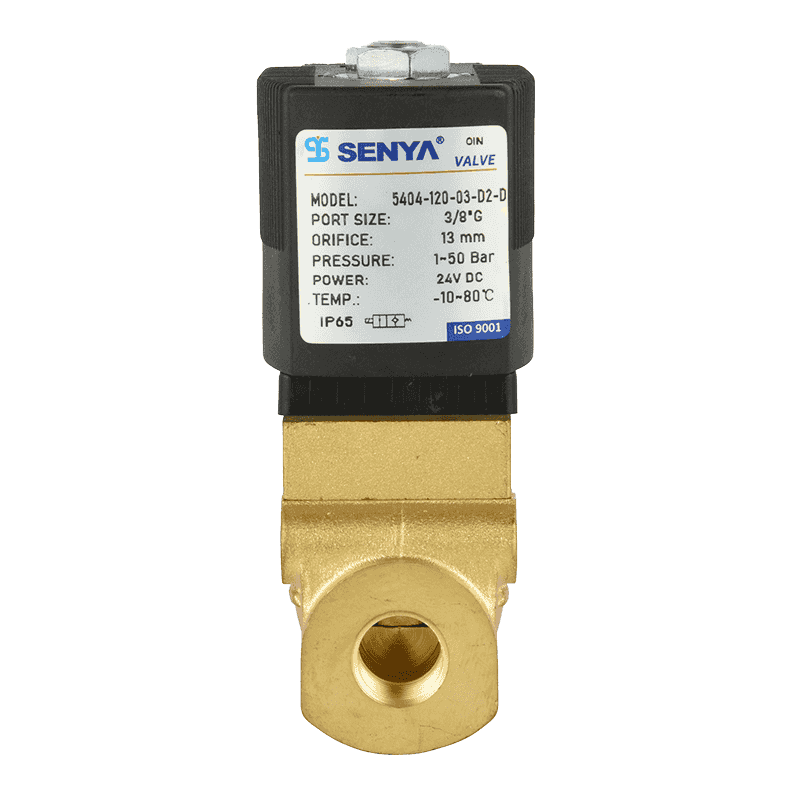
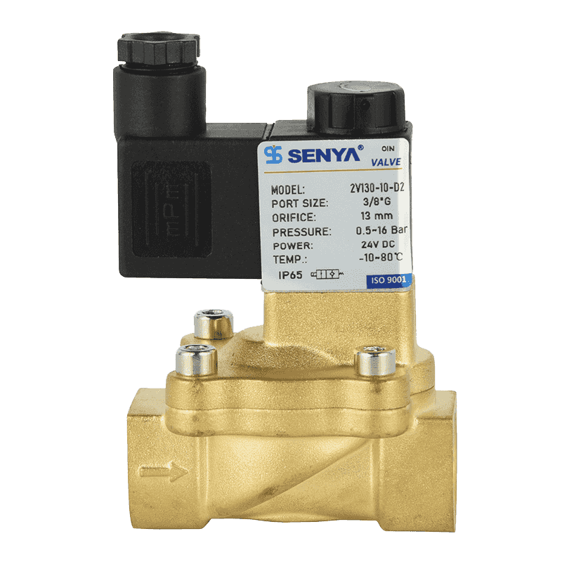
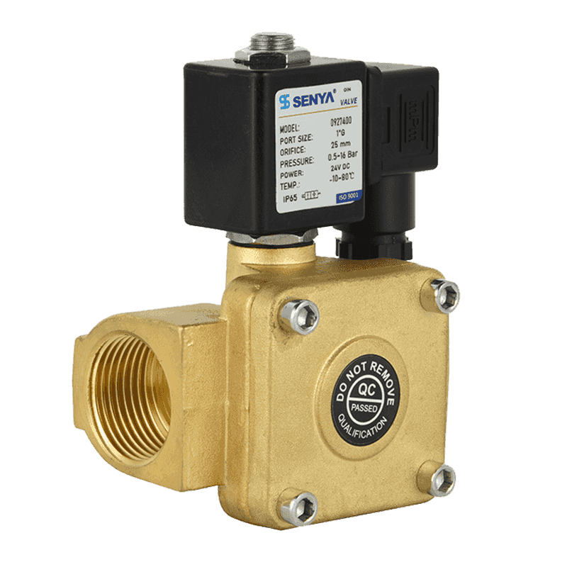
 A large water control 2/2 ways brass solenoid valve with high Impurity tolerance capacityhigh frequency pilot setView Product →
Commissioning is mechanical as well as electrical, because a coil that is energised but does not shift the spool is usually a flow or installation problem rather than a wiring one. This walkthrough of how to install and debug a 2/2-way solenoid valve covers the valve side of the same job.
AC and DC Coils Behave Differently on the Same Diagram
A DC coil draws a current that rises to a steady value and stays there. An AC coil does something less obvious: while the armature is open the impedance is low, so the coil draws a large inrush current. The moment the armature seats, inductance rises and current collapses to the holding value.
Three practical consequences follow:
- Switchgear and protection must be sized on inrush for AC coils and on steady current for DC coils. A fuse chosen from the holding VA of a 230 VAC coil very often nuisance-trips.
- Suppression differs. A DC coil is normally protected with a flyback diode across the terminals, cathode to positive. Across an AC coil that same diode is a short circuit; use an RC snubber or a varistor instead.
- Polarity only matters where something in the coil is polarity-sensitive: a built-in LED, a rectifier, or an external diode. A plain AC coil does not care which way round the plug is fitted, which is exactly why a reversed plug can go unnoticed for years.
The Control Side: PLC Outputs, Relays and Suppression
Solenoid valves are usually switched by a relay, a contactor or a PLC output. Two details of that circuit cause most of the trouble.
- Output type. A sourcing (PNP) output switches the +24 V leg; a sinking (NPN) output switches the 0 V leg. If the coil contains a diode or an LED, fitting the plug the wrong way turns that diode into a short circuit across the supply and the output stage fails.
- Suppression. Switching a coil off releases stored energy as a voltage spike. Without suppression the spike can reset controllers, disturb counters and shorten relay contact life. Suppression belongs across the coil, in the plug or at the terminal block, not at the PLC card.
Coil current at 24 VDC is small, under an amp for every common size, so a slow-blow fuse protects the conductor without nuisance tripping. For AC coils, size the fuse on the inrush value printed on the nameplate instead.
Wet, Outdoor and Washdown Installations
Ingress protection is defined by IEC 60529. IP65 means dust-tight and protected against water jets; IP67 adds temporary immersion. The rating on the label only holds while the gasket is present, correctly seated and undamaged, and the gland grips the cable sheath. In practice most water-in-the-plug failures are gasket failures rather than rating failures.
The plug is only half the installation, though. In car wash bays, food and beverage washdown areas, irrigation systems and outdoor tracking equipment, the coil has to survive the same conditions as the connector.
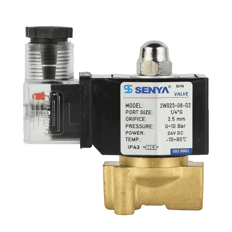
 Music fountain submerged water column control valve2/2 ways solenoid valve Brass solenoid Thermosetting coil, completely sealed and waterproof, can be immersed in waterView Product →
Commissioning Checks and the Faults That Follow Bad Wiring
The checks below confirm a new installation and catch almost every fault that a wrong diagram creates.
| Symptom | Likely wiring cause | Check |
|---|---|---|
| Valve hums but does not shift | Coil voltage below its tolerance band, often a long cable run or undersized conductor | Measure voltage at the coil terminals while the coil is energised |
| No click, but the indicator lamp is lit | Plug fitted 180 degrees out, coil on open circuit | Meter the two coil contacts for continuity and for supply |
| Coil fails shortly after installation | Wrong coil voltage, or a DC coil connected to an AC supply | Compare the nameplate with the measured supply |
| Controller resets when the valve switches | No suppression across the coil | Fit a flyback diode on DC, an RC snubber or varistor on AC |
| Water inside the plug | Gasket missing or deformed, gland not sealing on the sheath | Replace the gasket and re-terminate the cable |
Corrosion deserves a mention here because it is an electrical problem as well as a hydraulic one. Once a body, a terminal block or an earth contact corrodes, the earth path degrades and the coil can fail at a supply voltage that still looks correct on a meter.
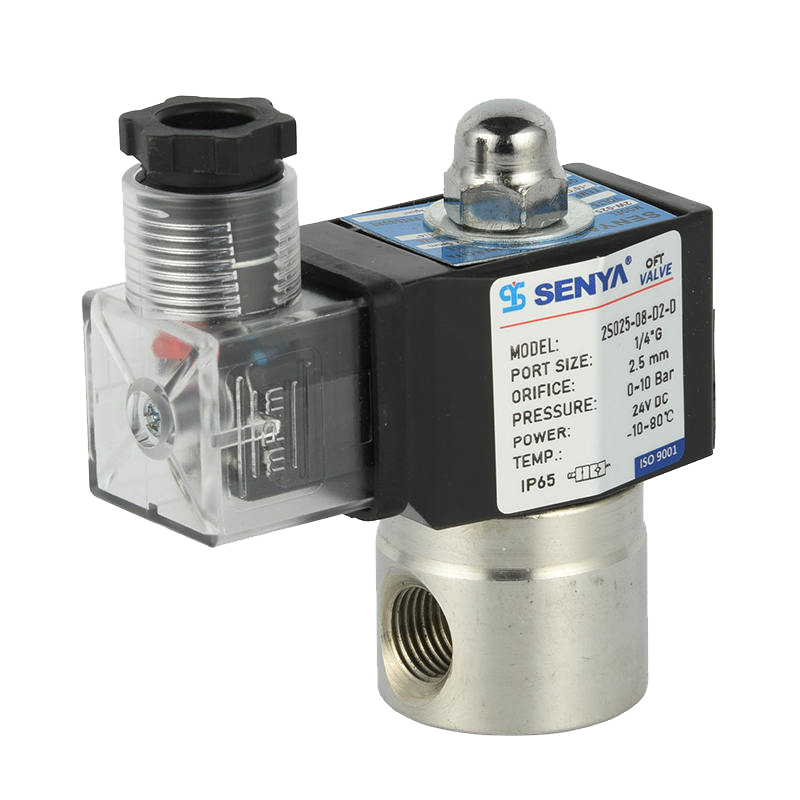
 Direct acting 2/2 ways stainless steel acid and alkali resistance normally closed solenoidZero differential pressure startView Product →
None of this is complicated, but it does need to be recorded. The diagram that saves the next shift is the one drawn on site: coil voltage, supply type, fuse class, output type, suppression fitted, and the date. SENYA has manufactured solenoid valves and pneumatic components since 1994 and exports to more than 30 countries, and its manufacturing background describes the machining tolerance and test equipment behind the coils. When a drawing and a nameplate disagree, trust the nameplate and update the drawing.
Frequently Asked Questions
Q1. What are the wire colours on a solenoid valve?
The connector has numbered contacts, not colours. On the supply side IEC 60446 and BS 7671 use brown line, blue neutral and green-yellow earth, while North American practice uses black, white and green. Always verify with a meter.
Q2. Does a solenoid valve have polarity?
Only if the coil contains a diode, an LED indicator or a rectifier. A plain AC coil can be connected either way; a DC coil with built-in suppression must be wired with the diode reverse-biased, cathode to positive.
Q3. Why does a solenoid valve coil burn out?
Most often because the coil is energised at the wrong voltage, or because the armature cannot seat through low pressure or debris, leaving an AC coil drawing inrush current continuously. It heats up and the insulation fails.
Q4. Do I need a flyback diode on a DC solenoid valve?
Yes, whenever the coil is switched by a PLC output, relay or solid-state device. Fit a flyback diode across a DC coil, or an RC snubber or varistor across an AC coil. A diode across an AC coil short-circuits the supply.
Q5. What is the pinout of a DIN 43650 Form A plug?
Form A (ISO 4400) has two coil contacts plus a protective earth contact. Most plugs place the coil between contacts 1 and 2 and mark the earth with the earth symbol, though some number it 3. Check the moulded numbers first.
Q6. How many amps does a 24 V solenoid valve draw?
Divide coil power by 24 V: about 0.08 A for a 2 W coil, 0.21 A for 5 W and 0.33 A for 8 W. Choose a slow-blow fuse above that steady value and check voltage at the coil on long runs.
.png?imageView2/2/w/326/h/326/format/jpg/q/75)
.png?imageView2/2/w/326/h/326/format/jpg/q/75)
.png?imageView2/2/w/326/h/326/format/jpg/q/75)
.png?imageView2/2/w/326/h/326/format/jpg/q/75)
.png?imageView2/2/w/326/h/326/format/jpg/q/75)