
 简体中文
 English
 Русский
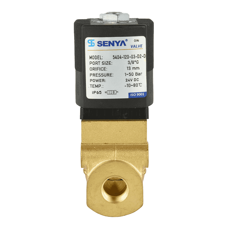
A replacement 2W-series brass valve arrives with the coil in one bag and the DIN plug taped to the body, and the question is always the same: which terminal gets the live wire, and which port is the inlet? Hooking up a solenoid is really two separate jobs. One is an electrical connection to the coil. The other is a fluid connection to the body. They fail independently, and a mistake in either one shows up in the same place: a valve that hums but does not switch, or a coil that runs hot for a week and then goes open circuit.
The short answer is that polarity almost never matters on an AC coil but can matter on a DC coil, the flow arrow cast or stamped on the body must point from inlet to outlet, and the earth pin on the plug is not optional. Everything else, from terminal torque to strainer selection, is detail wrapped around those three points.
Content
- 1 The short answer: three rules that cover most installations
- 2 Wiring the coil: the electrical half of the job
- 3 Plumbing the body: the fluid half of the job
- 4 Matching the valve to the line before you wire anything
- 5 Testing, and what to check when nothing happens
- 6 Solenoid valve hookup: frequently asked questions
The short answer: three rules that cover most installations
- Coil first. Read the nameplate before you strip a single wire: voltage, AC or DC, frequency, and wattage. A 24 V DC coil on a 230 V AC supply will not survive the first switch-on.
- Flow second. Two-way solenoid valves are directional, and pilot-operated versions are strictly directional. The arrow on the body is a hard requirement, not a suggestion.
- Earth third. A DIN 43650 Form A connector has three terminals, and the one marked with the earth symbol carries protective earth. Without it, a damp coil housing becomes a shock hazard and, in many installations, a code violation.
Everything below expands on those three points in the order you will actually work through them.
Wiring the coil: the electrical half of the job
Work through the sequence below in order. Skipping step one is the most common reason a brand-new coil dies on commissioning.
- Isolate the circuit and lock it out. Confirm with a meter at the point of connection, not at the panel breaker label.
- Read the coil nameplate. Note voltage, AC or DC, frequency in hertz, and power in watts or volt-amperes.
- Identify the terminals on the plug. On a DIN 43650 Form A connector, terminals 1 and 2 carry the supply and terminal 3, marked with the earth symbol, carries protective earth.
- Fit the cable gland and seal before terminating. The gasket between the plug and the coil housing is what makes the IP rating real; a pinched gasket quietly cancels it.
- Terminate the conductors. Use ferrules on stranded wire, keep strands out of the terminal, and tighten the small screws snugly without forcing them.
- Land the earth conductor on its dedicated terminal and check continuity back to the panel.
- Refit the plug, tighten the retaining screw, then energise briefly and listen for the click of the plunger.
Polarity: when it actually matters
On an AC coil, the two supply terminals are interchangeable and reversing them changes nothing. On a DC coil the situation depends on the coil design. A plain DC coil is also non-polarised, but coils fitted with a flyback diode, an integrated bridge rectifier, or an indicator LED are polarised. Wiring those backwards usually results in a dead short through the diode or an LED that never lights. If the coil housing carries a plus and minus marking, respect it.
Sizing the cable run: voltage drop is the real constraint
Coil currents are small. A 6 W, 24 V DC coil draws roughly 0.25 A, so conductor gauge is rarely limited by current-carrying capacity. What does bite is voltage drop over a long run. The chart below is a direct calculation using copper resistivity of 0.0172 ohm square millimetres per metre and the round-trip length of both conductors.
Insulation class tells you how hot the coil is allowed to run
Every coil carries an insulation class marking, and IEC 60085 sets the maximum hot-spot temperature for each class. This matters when a valve sits in an enclosure with other heat sources or when ambient temperature in a plant room climbs in summer. Running a Class B coil in a location that needs Class F is a slow failure, not an instant one.
Plumbing the body: the fluid half of the job
The electrical side decides whether the valve actuates. The fluid side decides whether it seals and whether it lasts. Three details cause most of the leaks and most of the warranty arguments.
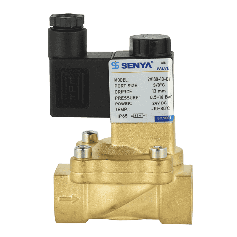
Flow direction comes first. Check the arrow on the body and the letters or numbers beside the ports. On a two-way valve, the inlet is normally the port opposite the arrow tail, and installing it backwards produces either a valve that will not open or one that leaks through when it should be closed. Coil orientation comes second: on most brass valves the coil can be rotated through a full turn by loosening its retaining nut, and it is far easier to do that before the ports are tight than after. Third, seal the threads properly. Two turns of PTFE tape, applied so the first thread stays bare, or a compatible thread paste, is enough. Tape fragments that break loose inside the pipe end up on the seat.
On hard-water or dirty-media lines, fit a strainer or a fine filter upstream. Brass bodies with a high tolerance for impurities will still pass grit through to the diaphragm seat eventually, and the cost of a Y-strainer is trivial next to a service call.
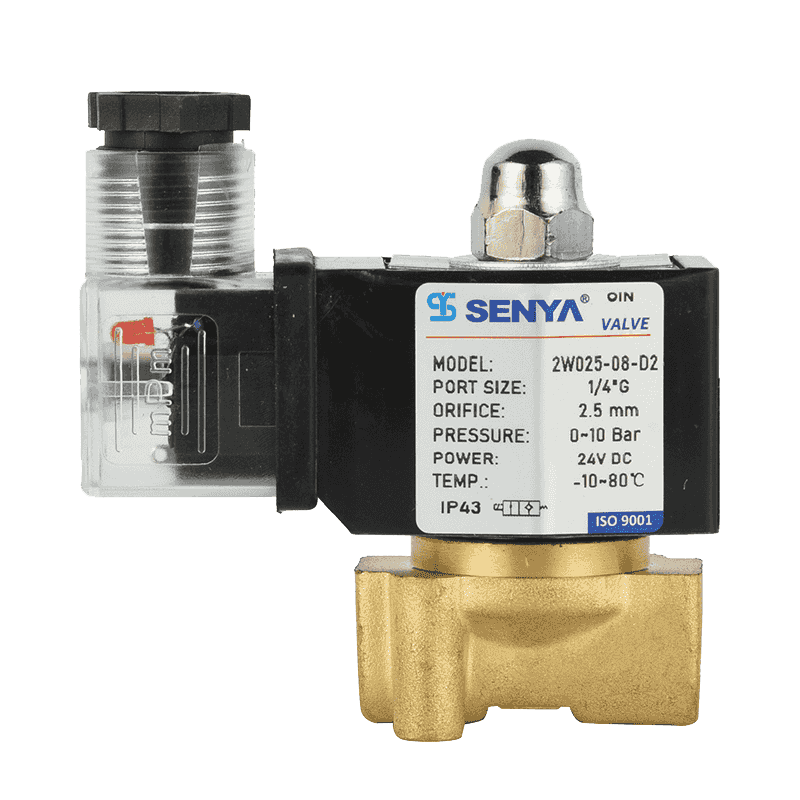
 2W Series Brass Direct-Acting Solenoid Valve for Impurity-Rich WaterLarge-flow brass 2W valve starts at zero differential pressure and resists impurity blockage, suited to dirty water lines and outdoor water control.View Product →
Matching the valve to the line before you wire anything
Body material and operating principle decide more about long-term reliability than any wiring detail. Pilot-operated valves need a minimum pressure differential across the valve to hold the plunger open, so they are a poor choice on gravity-fed or very low-pressure lines. Direct-acting valves open from zero pressure but draw a larger coil for the same orifice.
| Body material | Typical media | What to watch |
|---|---|---|
| Brass | Water, compressed air, neutral gases, light oils | Not suitable for ammonia or aggressive chemistry; dezincification risk in some soft waters |
| Stainless steel 304 | Mildly corrosive fluids, medical and food-adjacent lines | Higher cost and weight; check seal elastomer compatibility separately |
| Cast aluminium | Compressed air, dust collection pulse service | Poor resistance to water and condensate; requires dry air |
| Engineering plastic | Water treatment, dosing, light chemical duty | Lower pressure and temperature ceilings; UV exposure shortens service life outdoors |
Two further choices are worth settling early. For wash bays, irrigation headers or outdoor fountains, a waterproof coil and connector assembly removes the most common cause of repeat failure. For lines carrying mildly corrosive media or where washdown chemicals are present, a stainless steel body does the same job. SENYA has been manufacturing pneumatic components since 1994 and publishes full pressure, orifice and material data in its catalog, which is the fastest way to check a specific combination against your line conditions.
 Submerged Music Fountain Water Column Control Solenoid Valve2/2-way brass valve with sealed waterproof IP6X coil and fast response for submerged music fountain water column control.View Product →
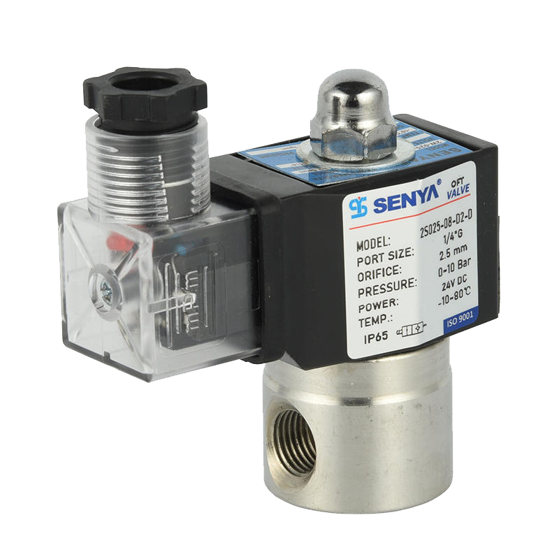
 2S Series Stainless Steel Direct-Acting Solenoid Valve for Acid and Alkali MediaDirect-acting normally closed 2S valve with SUS304/SUS316 body options and Viton seals for acid/alkali media, starting at zero differential pressure.View Product →
Testing, and what to check when nothing happens
Commissioning takes five minutes. Measure the coil resistance with the power off and compare it against the nameplate or a spare coil. An open circuit or a reading far below the expected value points to a burnt winding. Then energise and measure voltage at the coil terminals rather than at the panel, because that is where a loose ferrule or a long run shows up as a drop. A healthy valve produces a distinct click and a light vibration you can feel with a finger on the coil housing.
| Symptom | Most likely cause | Check first |
|---|---|---|
| No click, no flow | No supply at the coil, or open winding | Voltage at terminals 1 and 2, then coil resistance |
| Click but no flow | Valve installed against the flow arrow, or blocked pilot passage | Arrow direction, then the pilot orifice and upstream strainer |
| Flow will not stop | Debris on the seat, or worn diaphragm | Strip the valve and inspect the seat and elastomer |
| Coil hot and buzzing | Wrong voltage or frequency, or a stuck plunger | Nameplate against supply, then plunger freedom |
If the valve is new and behaves correctly on the bench but not in the line, the installation sequence is usually the culprit rather than the valve. A step-by-step commissioning walkthrough for two-way valves, including the checks that catch reversed ports and pinched gaskets before they become leaks, is worth reading before you close up the panel.
For a deeper walkthrough of installation and debugging, see this guide on installing and debugging a two-way solenoid valve.