
 简体中文
 English
 Русский
A packaging line stops at shift start because one 24 VDC solenoid valve on the glue station will not open. The coil is new, the valve body is clean, and the PLC output LED is on. The fault turns out to be a DIN plug fitted with the terminals reversed and no suppression across the coil. The output card survived; the coil did not.
Here is the short version. Wire a solenoid valve in this order: read the coil label and confirm voltage plus current, mount and earth the coil, terminate the plug with the switched line on pin 1 and neutral or 0 V on pin 2, measure coil resistance with a meter, then energize and confirm the valve shifts before you reconnect the process line.
The rest of this guide explains why that order matters, where the tolerances actually sit, and which mistakes destroy coils on real installations.
Content
- 1 What you are actually connecting
- 2 Read the coil label before cutting any wire
- 3 Eight steps to wire the valve
- 4 DIN plug pinout: what goes where
- 5 AC coil or DC coil
- 6 Cable length, voltage drop and burned coils
- 7 Surge suppression and PLC outputs
- 8 Wet, washdown and outdoor installations
- 9 Commissioning checks before you walk away
- 10 Frequently asked questions
What you are actually connecting
A solenoid valve is two devices sharing one housing. The body is a fluid component: ports, seals, a plunger or diaphragm. The coil is an electrical component: a winding of copper wire that generates a magnetic field strong enough to move that plunger. Wiring only ever concerns the coil side, which is why a "dead" valve is so often a coil, plug or supply problem rather than a fluid problem.
The coil slides over a fixed sleeve and is held by a nut. Electrical connection is made through a plug, usually a DIN 43650 form factor, that seats onto the coil terminal block. Three things must be right at that interface: the supply matches the winding, the plug is seated with its gasket square, and the earth conductor is connected on metal-bodied valves.
Read the coil label before cutting any wire
Every coil carries a label, and the label is the wiring instruction. Look for five items:
- Rated voltage, and for AC coils the frequency — 230 V AC 50 Hz and 230 V AC 60 Hz are different windings.
- Power in W for DC or VA for AC, which is what you need to calculate current draw.
- Duty cycle, usually 100% ED; short-duty coils overheat if held energized.
- Protection class such as IP65, which only holds while the plug gasket is intact.
- Voltage tolerance, typically ±10%, which is narrower than most people assume.
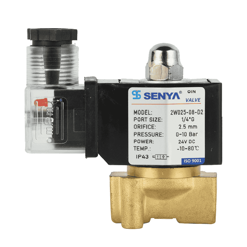
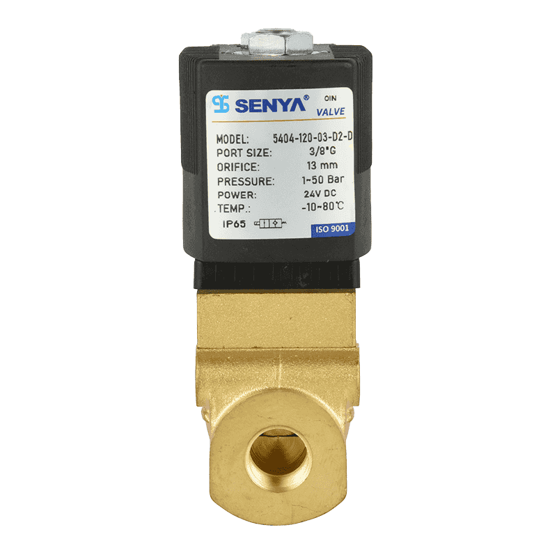
Two consequences follow. First, a 24 VDC coil drawing 0.2–0.4 A needs a supply and cable sized for that current, not for a signal. Second, an AC coil's inrush can be several times its holding current, which is why AC coils are normally switched through a relay or a suitably rated output rather than a small transistor card. Many water and air lines use a general-purpose brass body with a single fixed-voltage coil, such as the SENYA brass 2W series, and the labelling logic is the same.
 SENYA 2W Series Brass Water Control Solenoid ValveLarge-flow 2/2-way brass valve for water control, tolerant of particulate impurities, with voltage and plug variants to match system requirements.View Product →
Full coil and body options, including voltage variants and plug types, are listed in the 2024 SENYA product catalog.
Eight steps to wire the valve
- Isolate and lock off. Prove dead at the coil terminals, not at the panel breaker.
- Mount the valve and coil. Hand-tighten the coil nut; overtightening distorts the sleeve and the plunger sticks.
- Check coil resistance. A healthy winding reads roughly V²/P ohms — a 24 V, 5 W coil is about 115 Ω. Open circuit or near zero means a failed coil.
- Fit the cable gland and strip 6–8 mm of insulation. Use ferrules on stranded wire and leave no copper exposed past the terminal.
- Terminate the plug: switched line on pin 1, neutral or 0 V on pin 2, protective earth on the centre terminal.
- Seat the plug and tighten the centre screw. The flat gasket must sit square — a cocked gasket is the most common route for water ingress.
- Earth metal-bodied valves and check continuity from body to the panel earth bar.
- Energize and verify. Listen for the click, confirm the valve shifts, and check for leaks at the ports after the first cycle.
Route the coil cable away from VFD output cables and motor feeds. Induced noise on a 24 V coil line shows up as random valve chatter that reads like a mechanical fault.
DIN plug pinout: what goes where
Most industrial solenoid valves use a DIN 43650 (ISO 4400) three-terminal plug. The convention is consistent, but the moulded numbers are small and the plug body can be rotated 180° on the coil — so read the numbers instead of assuming the layout.
| Terminal | DC coil | AC coil |
|---|---|---|
| 1 | +24 V or switched positive | Switched line (L) |
| 2 | 0 V / common | Neutral (N) |
| Centre | Protective earth | Protective earth |
DC coils usually have no functional polarity — the valve opens either way — unless a suppression diode is built into the plug or the coil. If a diode, LED or RC module is inside the plug, reversing the supply will short the coil through that diode, so treat pin 1 and pin 2 as fixed.
AC coil or DC coil
| Aspect | AC coil | DC coil |
|---|---|---|
| Typical supply | 24, 110 or 230 V AC | 12, 24 or 48 V DC |
| Current at equal power | Lower | Higher — larger conductors needed |
| Inrush | Well above holding current | Close to steady state |
| Switching device | Relay or triac output | Transistor output usually sufficient |
| Suppression | RC snubber or VDR across the coil | Flyback diode across the coil |
Cable length, voltage drop and burned coils
Long runs are the quiet killer of 24 V installations. A coil that measures 24 V at the panel may see 20 V at the terminals, and magnetic force falls with voltage, so the plunger becomes sluggish or refuses to open. Near the lower edge of the ±10% tolerance band, valves often buzz instead of failing outright, which makes the fault hard to trace.
The fix is conductor size, not a bigger power supply. Keep total drop on the coil circuit under 5% at rated current and calculate it with the round-trip length, because both conductors count.
Surge suppression and PLC outputs
When a DC coil is de-energized, its collapsing field produces a spike that can exceed the supply several times over. Across a transistor output that spike is destructive; across a relay contact it produces arcing that erodes the contact. A flyback diode wired across the coil, cathode to positive, clamps it. Many plug assemblies already include a diode, LED and VDR module, in which case correct polarity is the whole job.
For AC coils, use an RC snubber or a VDR rather than a diode, and fit it at the coil, not at the panel. Suppression at the wrong end of a long cable leaves the spike free to travel.
Wet, washdown and outdoor installations
Water rarely damages a coil directly. It reaches the terminals through a poorly seated plug, and the resulting corrosion creates a resistive joint that heats and eventually opens the circuit. Two details matter more than the valve itself: the plug gasket and the cable gland entry direction. Route the cable so it enters from below with a drip loop, and use a plug rated for the washdown pressure you actually apply.
For lines that stay wet, a waterproof coil assembly rated IP65 combined with a well-seated gasket does more for reliability than any amount of dielectric grease.
 Music Fountain Submerged Water Column Control ValveSealed thermosetting-coil brass solenoid valve for submerged fountain water-column control, offering fast switching and IP6X protection for wet installations.View Product →
Commissioning checks before you walk away
- Coil resistance matches the calculated value for its rating.
- Supply voltage measured at the coil terminals, with the coil energized, not at the panel.
- Earth continuity from valve body to the panel earth bar, below 1 Ω.
- No leak at the coil nut or port threads after three complete cycles.
- Coil surface temperature stable after 30 minutes; a coil too hot to touch briefly is overloaded or over-voltaged.
If the valve clicks but does not pass fluid, the problem has moved to the fluid side: insufficient differential pressure, a blocked pilot passage, or a coil fitted to a body it was not matched with. Wiring changes nothing at that point, so switch to the installation and debugging sequence for 2/2 way solenoid valves and work through the fluid-side checks in order.
Frequently asked questions
Q1. How do I know what voltage my solenoid valve needs?
Read the coil label, not the valve body. Coils are interchangeable within a family, so a second-hand body may carry a 110 V AC coil while the machine expects 24 V DC. The moulded voltage and frequency on the coil is the only number that governs wiring.
Q2. Can I wire a 24 V DC solenoid valve to a 230 V AC supply?
No. The winding will fail almost instantly and may rupture the coil housing. If only mains is available, use a 230 V AC coil, or a small transformer or switching supply feeding a 24 V DC coil through a relay.
Q3. Does polarity matter when wiring a solenoid valve?
Usually not for a plain DC or AC coil, because the field reverses with the current. It matters as soon as a diode, LED or RC module is built into the plug or coil, since a reversed supply then shorts through that component.
Q4. Why do solenoid valve coils burn out?
The common causes are wrong supply voltage, a short-duty coil held energized continuously, missing flyback suppression on a PLC-driven DC coil, and moisture reaching the terminals through a cocked DIN plug gasket.
Q5. How do I wire a solenoid valve to a PLC output?
Check the output's current rating against the coil current and add a flyback diode across the coil. For AC coils, or DC coils drawing more than the card allows, interpose a relay so the PLC only switches the relay coil.
Q6. Can I replace a coil with a different voltage?
Yes, coils are replaceable parts and the same body often accepts 12 V DC through 230 V AC coils. Match the bore and sleeve, keep the plug rating intact, and update the panel label so the next technician does not repeat the mistake.